This application note explains programming tools that are useful for rollerdie makers: projecting an XY program on XA axes while keeping dimensions and vector feed, internal sharp corners cutting, and repetitions. Any XY program can be projected, including engraving and drilling canned cycles.
M12 R_   start projecting Y on A
M13      end Y to A and cancel zero-shift
M12 and M13 are defined in the machine.cnx file as follows (for A= 4th axis):
[12] Y to A transformation
leader(4,2) leader(2,0)     \A is lead by Y, Y is ignored
gearbox(4,180/Ki/pi/R)      \A ratio: deg/mm or deg/inch
                            \Use negative ratio to reverse A
trans lead, gear            \Start
putplc(78,4)                \4th axis is displayed in graphic
mend

[13] Cancel Y to A transformation
trans off                   \cancel m12
g52 putplc(78,0)            \cancel zero-shift
mend
Before calling m12, Y must be zero.
Z=0 should be set at the rollerdie surface.
M12 is called with the rollerdie radius given under R. This code works in both inch and metric.
When M12 is active any Y command moves A; Y-displacement and the programmed feed are applied to the surface of the rollerdie. Also the graphic display shows XA rather than XY.
M12 sets Y-zero to current A, which needn't be zero. In the following example Y-zero will be A-180:
g x_ y z_ a-180 m12 R2M13 is the default when starting a program and after M2 or Reset.
Rotary axis always uses feed in mm/min as deg/min.
The projection of Y on A converts feed to deg/min so that the programmed vector feed is maintained.
For a roller radius of 57.296 mm (180/pi, 2.2557") one mm at the perimeter is one degree. For a larger radius A turns slower and for smaller radius A turns faster. Based on the max programmed feedrate, if an axis reaches the feed limit all axes slow down to follow the programmed path.
If constant vector feed is important the programmed feed should not cause X and A to reach their respective limits.
M61 start internal corners
M60 end
M60 and M61 are defined in the machine.cnx file as follows:
[60]
putplc(77,0)
mend

[61]
putplc(77,TR*Ki+1)
mend
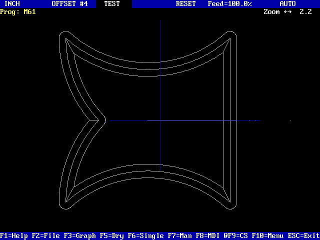
With m61 active, at every internal corner the tool stops and then moves to the programmed corner while Z goes to Z=0, then back. The motion is interpolated so that the tool remains tangent to both sides of the corner. This function covers all corners – line-line, line-arc, arc-line, arc-arc.
M61 doesn't affect external corners so if desired it can be turned on at the beginning of a program.
M60 is the default when starting a program and after M2 or Reset.
|
|
\#10 roller radius
\#11 X center to center
\#12 repetitions in A
\#13 repetitions in X

m3 s5500
g y z.1 a m12 R#10                     \start Y to A

for #2=1 to #12                        \repeat along X
  for #3=0 to #13                      \repeat along A
    if #3==#13 then break end
    g52 y=gil(0,2*pi*#10) x=(#2-1)*#11 \zero shift

    \xy program

  next #3
  if #2<#12 then                       \skip on the last time
    m13                                \cancel m12 and g52
    g x#11 y a m12 R#10                \electronically rewind A then resume Y to A
  end
next #2

g z+.2 m2
Note: M2 cancels M12 therefore M13 is required only if the program continues with direct commands to A.
A program, provided by Numeryx, can be used to automate the Repeat process.
Currently the program supports 3 shapes: Circle, Oval and Rectangle. However, the user can add his own shapes.
Upon CS the following menu is displayed:
|
|
|
|
|
|