B-Tilting Head + C-Rotary Setup
An-102g, Copyright © by Gil Hagiz
Last updated Apr-19-2007
For version 6.11 and later
Introduction
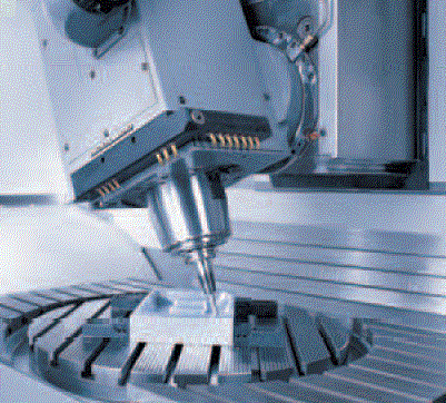
This application note describes the setup of a 5-axis machine employing B tilting head and C rotary table.
The TCP capability is provided by a separate BIN file. Without this file the machine can work as a regular 5-axis non TCP machine.

Dekel-Maho-Gildemeister
General
- This configuration is usually used on vertical machines.
- There maybe offsets or misalignments in the head that can be compensated by software.
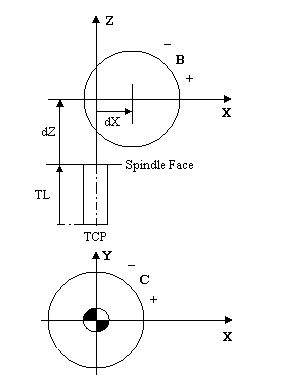
- The standard positive rotation of a rotary head axis is CCW when looking from the positive direction of its perpendicular axis.
The standard positive rotation of a rotary table axis is CW when looking from the positive direction of its perpendicular axis.
This is the default of the TCP files.
However, in some existing machines one or both directions may be reversed, so it can be set as desired.
H-Modes
H5 should be used for all programs that requires TCP. In this mode the XYZ coordinate system is that of the part, not the machine. Drilling canned cycles move in the tool direction.
In Manual, H5 moves the machine XYZ, same as drilling, and H3 is used to move in the part coordinates.
Preparation
This set up can be performed by a superuser only.
To avoid unintentional set up, the superuser has to change the security level in plc@50 to 0.
In MDI type: @50=0
Line numbers for setup data relate to the machine.cnx file, in the machine data area after line n30000.
Before you start:
- The file hbrc5.bin should be copied to the C:\RR directory (or wherever ncplus.exe is).
- The INI file must have the lines:
Axes=xyzbc
Model=hbrc5
No directory should be entered; the TCP file should be in the same dir as ncplus.exe.
Decide what is the positive direction you prefer for the rotary axes.
If for one or both axes the positive direction is reversed (see figure below) add /b /c switches to the command. For example:
Model=hbrc5 /b /c
At least one space should separate the switches from the file name.
Note: these switches are used for the TCP calculations, not for reversing the direction.
- B and C must be the 4th and 5th axes of NCPlus. If B or C are not the 4th and 5th axes of the Delta Tau use the DT mapping (see 6.11 upgrade).
For example, if DT's 4th axis is used for the spindle, enter in the INI file:
Axes=xyzbc
dtsx=12356
- Use the latest ncplus.msg file (Apr-17-2007 or later).
- Replace cnx-111 (should be used with 6.11 integrated incremental/MPG menu):
[111] Incremental Jog
key=2-scan(@48&$07)                     \key=-1,0,1
f=5000/Ki
if (#101=@48&$0F00/$100) then           \incremental
  if #101>4 then mend end               \error- ignore
  #150=10**(#101-5+((Ki==1) or (@49>=4))) \-5: inch, -4: mm or deg.
  if @133 then g0 g100 g8 @@+=@133*#150 @133=0  \MPG
          else g1 g100 g9 @@+=key*#150 end      \incremental
else                                    \continous
  if @49>=4 or H==0 then mend end
  g1 g100 g9 if key then @@+=key*1000 else @@ end
  @48&=~$07                             \done
end
mend
- Add line in cnx-114 to display F5=H in Manual and SetHome:
[114] Places
. . . .
     if @63&2==0 then
       color(lightgreen,black) locate(29,1) pr getini$('message'),' ',ver$;
       if #190&3==3 then locate(30,26) color(white,blue) pr 'F5=H'; end
. . . .
- Comment out Cnx line n21, as all axes should move simultaneously upon G0:
\n21 z \g0 priority
- In plc-2 add display mode for TCP (plc@40 holds the TCP mode under H):
[2]
. . . .
@320=@399+10               \abs - distance
if @40 then if @399==0 then @320=9 end end
- Ensure that Home setting in plc-3 for B is disabled:
[3]
. . . .
@74=$08
- In plc-4 add the command to use F5 for switching TCP-mode (H-mode):
[4]
    . . . .
    if @59<>0 then else
    . . . .
    end
    if @59==1 or @59==5 then              \Man, SetHome
      if @88==1063 then kb(1194) end      \F5 switches H-mode
    end
  end
end
- In plc-9 add the display mode TCP Abs:
[9]
 . . . .
 9\TCP Abs  \
10\Absolute \
11\Dis To Go\
- In line n13 enter the signed offset dX, as described in the drawing below.
This offset may be zero. If no info is known enter zero. Data in line n13 must be in mm
Z offset is the distance from the spindle face to B-center, so that tool length will be measured from the spindle face. This information should be obtained from the machine builder.
For example, enter in line n13:
n13 x z150
- If C has no limits and is free to rotate indefinitely enter C in line n19 (with S):
n19 S... C1
- All axes must be able to move freely, after the servo drivers have been set.
- All axes must have their Reference procedure working, all references set, and table limits set.
- An indicator is required for squareness and similar measurements.
- Use a round bar in the spindle if the spindle itself cannot be measured.
- All motions are done in H0 mode with offset #0 (machine zero), unless otherwise written.
Setup general
To set the machine zero for an axis proceed as follows (B is used as an example):
- Set the reference
- Jog B-axis to the desired zero
- Select Set-Home mode
- Select machine zero: press alt-0
- Open the data input line by pressing <Enter>
- Type the axis letter B and press <Enter>
- If you are not at zero but say at B15 type:
b15 <Enter>
- The zero for B becomes effective immediately
Notes:
- In SetRef mode (and ChkRef) the display shows the distance of the axis from its electronic reference.
- In all other modes the display shows the distance from the current Home.
- Home #0 is the machine zero.
Setup B-zero
- Reference B.
- Use a round bar in the spindle.
- Set B to vertical position with the jog pushbuttons.
- Use an indicator; move Z up and down and move B until the round bar is in line with Z.
- Enter in Set-Home for offset #0:
b <Enter>
Setup C-axis
- C=0 can be set anywhere at your convenience.
- At this position, the table's YZ coincide with the machine's YZ.
- Enter in Set-Home for offset #0:
c <Enter>
- The user can set Home (Fixture Offset) for C-axis anytime to align the work-piece with the XY axes.
Tool Length
Tool length is measured from B-pivot. However, tools can be measured from a more convenient place, like the spindle face, while the distance of this place from B-pivot is entered under Z in line n13.
If the distance to the spindle face is not known it can be measured on the machine but the accuracy depends on the accuracy of B.
To measure the distance on the machine:
- Use a calibration ball tool with a known length.
Note: tool length is measured to the center of the ball.
- Set B to zero.
- Set an indicator touching the ball from the X direction, then move X away.
- Turn B to +30 (or -30, whichever is more convenient).
- Move X and Z until the indicator touches the ball at the same point.
The difference in X is half of the total length from the TCP to B-pivot.
Subtract the tool length from the total length and enter the results in mm in line n13 under Z.
Setup XY
- Set B to zero.
- Load a dial indicator into the Spindle.
- With the indicator, set XY at the center of the C-table.
- Enter in Set-Home for offset #0:
x y <Enter>
X-offset
X offset can compensate for misalignment between the spindle axis and the B-axis.
To measure the offset B should be turned to +90 and -90 deg. Since many machines don't have that travel, +30 and -30 can be used instead.
- Set B to zero.
- Use a round bar in the spindle.
- Turn B to +90 and then to -90 (or +-30); measure the difference in Z of the bar.
X-error is half of the difference for +-90 and exactly the difference for +-30.
The error is POSITIVE if Z at the plus is higher than Z at the minus. (Provided that the positive direction of B is CCW).
- Enter the result in line n13 for X.
Final test
- Set B to zero.
- Use the ball tool in the spindle. Enter its length in the tool table and make sure that it is active.
- In Manual, set TCP mode H3.
- Repeat the Tool length test, this time the ball is not supposed to move.
- Repeat the offset tests for B.
- Zero 3 indicators on the table touching the ball.
- Move B and C. There shouldn't be any offset errors.
- Jog the axes in TCP mode and ensure that the Cartesian coordinate system is attached to the tool and the rotary table.

